Programming
/ OMR
/ Optical Mark Recognition
In This Topic
Introduction
Designing and creating an Optical Mark Recognition application (OMR) or an OMR plugin within your main application is a daunting task for most developers.
The main reason is the variety of components involved in the process and finding ways to integrate them together in a manner, that would eventually be presented as a smooth user experience.
In GdPicture, from the very beginning, we designed those "parts" to work both as standalone components – to be used in different jobs and to be easily integrated together to produce a smooth user experience.
Understanding that integration process, however, requires a good understanding of the components themselves first, and then dive into how to combine them.
This is what this tutorial aims to do.
What is Optical Mark Recognition?
Optical mark recognition (also called optical mark reading, or OMR) is the process, in which we use hardware, software or both to capture the human marked filling of multiple choice questions, questionnaires with true or false fields, and all types of document forms.
Those types of "fields", which we call OMR Fields, occur in almost every form, be it a standard tax or visa form survey, where you will have to specify your sex, and whether you are employed or not, or multiple choice exams like the SATs, where the OMR Fields are the dominant and most important type of data on the form.
Using GdPicture, you can scan those documents and set up a system, that will tell you, whether each OMR Field is filled or not in a fast and accurate manner.
Components of a software OMR System
Each OMR system, no matter what the type of the document it will handle, has two main components:
-
Template: This usually is a non-filled document, where you specify the location of the data you want to extract. This "data" is split into two parts:
-
Anchor: A logo, black rectangle, or some solid object at the edge of the document we know will occur in every filled form.
This is used to measure translation of scanned filled forms, but more on that later.
-
OMR Fields: Those are the locations of the fields, which humans are required to fill.
GdPicture uses rectangles surrounding those fields to specify their location for the recognition algorithm.
This could be done via code, or mouse interaction, and is explained in the Process section of this tutorial.
-
Scanned forms: These are the same forms as the template, but with the human-marking data on them.
Basically, they are the documents we wish to extract the information from.
Types of OMR Fields
While there are numerous types of OMR fields, we aim to show the most common of them just to give a better understanding of what they are.
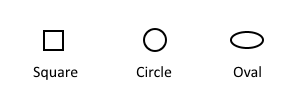
In multiple choice exams they often have characters inside of them:
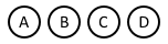
No matter what the shape or the content is, GdPicture OMR Detection functions can deal with them and adjust the recognition process accordingly as long as you specify the shape and whether or not it contains a character.
Problems causing bad OMR
Before we move on to our system design, we have to understand the system itself to detect areas, which could hinder the quality of our results.
In OMR systems, there are three known enemies:
-
Low DPI Images: Low DPI images are images acquired at 150 dots per pixel and less. They affect the quality of the image and in turn, the quality of the OMR Fields and the content inside of them. They also lead to the next problem.
-
Small Fields: If the OMR fields are too small, in many cases the decision process will depend on just a few pixels, making the data available to the recognition algorithm too small to make an accurate decision and the error margins bigger.
-
Translation due to scanning: The most important problem. The locations of the OMR Fields in the scanned filled document will never be the same as the locations specified in the template document. Why?
There are two main reasons behind this phenomenon:
- Location of document in the scanner will never be exactly the same as the location of the template document in the scanner. This is simply just a fact of human life, where it is hard to keep the alignment 100% correct.
- Stretching along both axes due to the feeding mechanism in the Automatic Document Feeder of the scanner, if it is used.
Not to worry though, GdPicture has developed a specific engine called the Anchoring Engine to help you measure this translation and amend your data locations.
The first two problems, however, can be easily remedied at form design time by scanning at 200-300 DPI and making the OMR Fields large enough to contain more than a few pixels inside of them.
Anchoring: Overcoming the Translation problem
Remember in the "Components of the OMR System", one of the parts of the Template form was an Anchor, which was defined as: A logo, black rectangle, or some solid object at the edge of the document we know will occur in every filled form.
In the “Problems causing bad OMR” section we mentioned, that those Anchors are used to measure translation between the template document and the scanned filled forms. How is this done?
The idea behind choosing a logo or a solid rectangle or object is that no matter what sampling is used, it shall occur in every document with enough data (black pixels) to recognize it again.
If we search for this "Anchor" in the filled document, find it and register its location, we can compare its new location to its location in the template document.
The difference between the two location in the X and Y axes IS the translation. This translation is the translation of the whole document.
Now if we apply this translation to the OMR Field rectangles specified in the template document, they will be at their correct location (because they suffered the same translation), and thus, we know the location of the OMR Fields in the filled document.
Too complicated? Are there too many concepts coming in together? Read the next section.
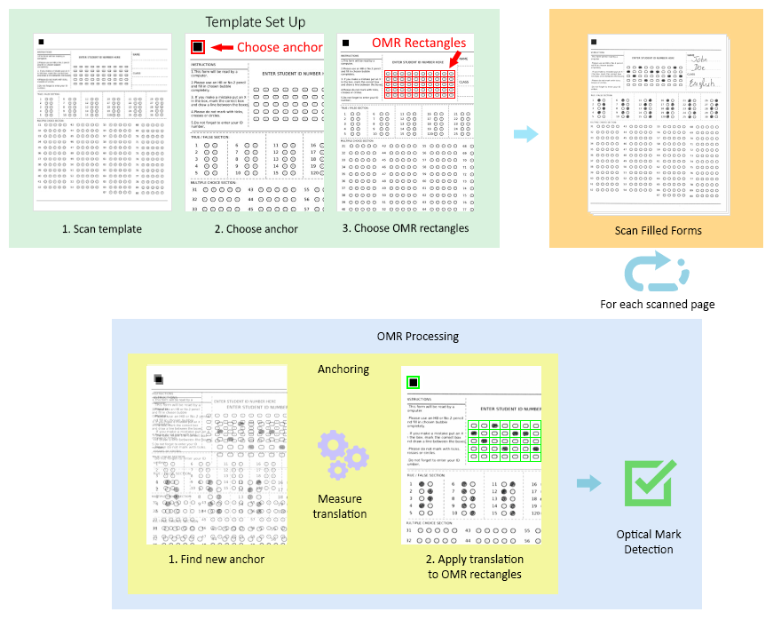
A look from outside: How it all fits together
In the bellow diagram, you can trace the steps of the OMR process beginning from how to set up the template, all the way to the recognition process.
We will go through each step and show, how to implement them via code.
The process
Template set up
Scanning the template
GdPicture comes equipped with TWAIN and WIA scanning drivers support to enable you to control almost any type of scanner via software.
Seeing as this is not the main topic for this tutorial, please have a look at our TWAIN and Scanning demos and samples to understand how to scan an image via GdPicture.
For now, we will assume, that you have your template image scanned and its GdPictureImage Identifier is named "templateId".
Creating the template anchor
Creating the anchor is done via the CreateAnchorTemplate function. All you have to do is specify the coordinates of the rectangle surrounding the anchor.
This can be done via code, by specifying the exact values, or via mouse, by using the GdViewer.
Using the GdViewer to specify the anchor position via mouse
In the following code, we show how to capture the MouseUp event of the GdViewer, and get the coordinates of the Rectangle of Selection in the GdViewer, and set them to be the coordinates of the Anchor Template.
| Using the GdViewer to specify the anchor position using the mouse |
Copy Code |
//We assume that GdPicture has been correctly installed and unlocked.

//We assume a GdViewer object called GdViewer1 has been created and painted on the form.

GdPictureImaging oGdPictureImaging = new GdPictureImaging();

IntPtr anchorTemplate;

int anchorLeft;

int anchorTop;

int anchorWidth;

int anchorHeight;

//Loading the image from a file.

int template = oGdPictureImaging.CreateGdPictureImageFromFile("template.tif");

//Checking if the image has been loaded correctly.

if (oGdPictureImaging.GetStat() != GdPictureStatus.OK)

{

    MessageBox.Show("The image can't be loaded. Error: " + oGdPictureImaging.GetStat().ToString());

}

else

{

    GdViewer1.DisplayFromGdPictureImage(template);

}


/// <summary>

/// On the Mouse UP event on the GdViewer, create an anchor template.

/// </summary>

/// <param name="eventSender">The object which the event has occurred on.

/// <param name="eventArgs">The events data.

public void CreateOMRANCHOR(System.Object eventSender, System.EventArgs eventArgs)

{

   //Checking if a rectangle of selection has been painted on the GdViewer.

   if (GdViewer1.IsRect())

   {

   //Getting the location of the selection on the document.

   GdViewer1.GetRectCoordinatesOnDocument(ref anchorLeft, ref anchorTop, ref anchorWidth, ref heightArea);


   //Setting the anchor template.

   anchorTemplate = oGdPictureImaging.CreateAnchorTemplate(template, anchorLeft, anchorTop, anchorWidth, anchorHeight);

   }

} |
As you can see, the four parameters anchorleft, anchorTop, anchorWidth and anchorHeight hold the position of the rectangle selected via mouse.
If the mouse selection selected a rectangle surrounding the anchor, the contents of that rectangle will constitute the anchor, when the function CreateAnchorTemplate is called.
Choosing OMR rectangles
Similar to point two, each OMR rectangle surrounding an OMR Field can be chosen via mouse on a GdViewer.
All you have to do is save the coordinates of the rectangle of selection in the GdViewer.MouseUp event onto the entry of the rectangles array.
This is a good place to mention, that if you have say 50 OMR Fields, you should create a rectangle array of length 50.
The OMR Detection function takes this rectangle array as a parameter and use it to remeber the locations of the OMR fields they are to evaluate.
In the following code example we show how to create a rectangle array of length “8”, assuming that you have “8” OMR Fields, and fills their coordinates one by one via mouse upon creating a rectangle of selection on the GdViewer:
| Choosing OMR Rectangles |
Copy Code |
//We assume that GdPicture has been correctly installed and unlocked.

//We assume a GdViewer object called GdViewer1 has been created and painted on the form.

GdPictureImaging oGdPictureImaging = new GdPictureImaging();

Rectangle[] omrRECT = new Rectangle[8];

int currentRect = 0;

//Loading the image from a file.

 int template = oGdPictureImaging.CreateGdPictureImageFromFile("template.tif");

 //Checking if the image has been loaded correctly.

if (oGdPictureImaging.GetStat() != GdPictureStatus.OK)

{

   MessageBox.Show("The image can't be loaded. Error: " + oGdPictureImaging.GetStat().ToString());

}

else

{

   GdViewer1.DisplayFromGdPictureImage(template);

}


/// <summary>

/// On the Mouse UP event on the GdViewer, create a rectangle Rectangle of Selection of the GdViewer.

/// </summary>

/// <param name="eventSender">The object which the event has occurred on.

/// <param name="eventArgs">The events data.

public void CreateOMRRect(System.Object eventSender, System.EventArgs eventArgs)

{

   //Initialize variables to hold the position of the rectangle of selection on the document

   int leftArea = 0;

   int topArea = 0;

   int widthArea = 0;

   int heightArea = 0;


   //Checking if a rectangle of selection has been painted on the GdViewer.

   if (GdViewer1.IsRect())

   {

      //Checking if we have already set up all OMR Fields locations.

      if (currentRect > 7)

      {

         return;

      }

      //Getting the location of the selection on the document.

      GdViewer1.GetRectCoordinatesOnDocument(ref leftArea, ref topArea, ref widthArea, ref heightArea);

      //Setting the OMR Rectangle.

      omrRECT(currentRect).X = leftArea;

      omrRECT(currentRect).Y = topArea;

      omrRECT(currentRect).Width = widthArea;

      omrRECT(currentRect).Height = heightArea;


      //Incrementing rectangle counter.

      currentRect = currentRect + 1;

   }

} |
We create the array of rectangles omrRECT, which we populate with the coordinates of the GdViewer selection rectangles one by one.
To achieve that, we just create a counter currentRect and use it to index the array, each time we enter a new rectangle, we increment it by one.
Do not forget to check, if you have already set up all rectangles in omrRECT, before you try to index a new entry and set it up.
Scanning filled forms
Again, this step, like scanning the template, is not in the scope of this tutorial.
For information on how to scan multiple files in a fast manner, please have a look at the Twain Scanning – Asynchronous sample in your GdPicture directory.
For the purpose of this tutorial, we shall assume that you have scanned your filled forms and stored their identifiers in an array of integers called "filledForms".
OMR processing
For each scanned filled document in "filledForms", we must measure the difference in the position between the anchor found in the filled form and the original anchor position in the template. Then we need to apply the same difference to each OMR rectangle, then send those rectangles for recognition.
Here is how we do so.
Anchoring
After we created our anchor template called “anchorTemplate”, we can now search for that anchor in every filled document.
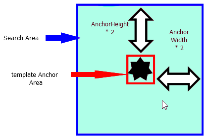
To find an anchor in a document, you must provide the following to the FindAnchor function.
- The document you are searching in
- An anchor template
- Search mode, whether speed or accuracy is preferred
- The search area
Please note, that the bigger the search area is, the more time it will take the function to execute. In the following code, we shall make the search area 5 times each dimension of the original anchor.
| Anchoring |
Copy Code |
//parameters for the new location of the anchor

int NewLeft = 0;

int NewTop = 0;

int NewWidth = 0;

int NewHeight = 0;


//accuracy of the recognition process

double Accuracy = 0;


//Calculating the width of the original anchor divided by 2.

int doubleWidth = anchorWidth / 2;

//Calculating the height of the original anchor divided by 2.

int doubleHeight = anchorHeight / 2;

//Finding the anchor.

oGdPictureImaging.FindAnchor(filledForm, ancorTemplate, OMRMode.FavorSpeed, anchorLeft - doubleWidth, anchorTop - doubleHeight,

anchorWidth + doubleWidth, anchorHeight + doubleHeight, ref NewLeft, ref NewTop, ref NewWidth, ref NewHeight, refAccuracy); |
In the above code, filledForm refers to the GdPictureImage Identifier of the current filledForms index. It is assumed, that you loop through your filledForms array and get it.
The two parameters doubleWidth and doubleHeight are calculated to enlarge the search area from the area of the original anchorTemplate to 25 times that area, by padding both amounts respectively, to each of the four parameters of the search rectangle.
Of course, the above is not a golden rule. It is just a suggested value and the actual values, that you should use, depend on the type of anchor, that you have along with its size and scanning process. Also please note, that the larger the search area is, the slower the algorithm will run, the smaller, the faster.
Measure Translation
Now when we have located the position of the anchor in the filled document, we can compare it to the location of the anchor in the template.
For example, let us assume, that the position of the template anchor in the template was in pixels at (50, 50). And that it was found in the filled form at position (55, 48).
Then the X translation would be: 5 pixels and the Y translation would be: -2 pixels
The bellow code demonstrates how easy it is to calculate the translation once you have the location of the template anchor and the filled form anchor:
| Translation |
Copy Code |
int xDifference = NewLeft - anchorLeft;

int yDifference = NewTop – anchorTop; |
Apply translations to OMR rectangles
All we have to do now is make a copy of the original omrRECTS array and deviate the X and Y locations by the translations measured in the previous step, here is how:
| Apply translation |
Copy Code |
Rectangle[] filledRECT = new Rectangle[8];


for (int i = 0; i <= 7; i++)

{

   filledRECT[i].X = omrRECT[i].X + xDifference;

   filledRECT[i].Y = omrRECT[i].Y + yDifference;

   filledRECT[i].Width = omrRECT[i].Width;

   filledRECT[i].Height = omrRECT[i].Height;

} |
Now you have eight rectangles in an array called filledRECT, that correspond to the locations of the OMR Fields in the current filled document.
Optical Mark Detection
Now it is finally time to get the results of our OMR Fields in the filled document.
All we have to do is call one of the OMR Detection functions with the appropriate overload depending on our need.
-
Categories of OMR Detection functions
OMR Detection functions are splitted into two categories depending on the shape of the OMR Field:
While it might seem that Oval and Circular OMR fields should be grouped together, the “closeness” of the X and Y axis dimensions makes Circular more similar to Square fields than to Oval.
Each of those two groups has many overloads that do the following:
- Make automatic detection without the need of any other specifications (recommended in most cases).
- Make detection based on a parameter, that specifies, whether or not the OMR field/fields contain characters.
- Make detection based on a sensitivity parameter, that controls, how much “filling” each field needs to have to be counted as filled or not. It also returns a “Confidence” array, that corresponds to each field’s result’s confidence.
For more information on all the overloads, please visit our documentation guides, here and here.
-
How to obtain the results via an OMR Detection function
We shall now show how to create an array of Integers called Results to store the results of the detection process in.
Each index in the array corresponds to the result rectangle of the same index in the array of rectangles "filledRECT", that was supplied to the OMR Detection function.
| OMR Detection |
Copy Code |
int[] Result = new int[8];

//Call OMR Detection function

//Automatic Detection

//8 OMR Fields

//Each field as a character inside of it

Result = oGdPictureImaging.OMRDetectOvalMarks(filledForm, filledRECT, 8, true); |
Now you should have the results of all eight OMR Fields.
For example: Result[3] corresponds to the result of the 4th OMR field, or in other words, to the OMR field that has the location filledRECT[3].
If Result[3] = 0, then the 4th OMR field was not filled, else if Result[3] = 1, then the 4th OMR field was filled.
Repeat Step "OMR Processing" for each and every scanned filled form.
Conclusion
The OMR Process while daunting at first, is easy and logical once you understand all the components.
The above tutorial is a mere bone structure of the process. Most application decide to create a TemplateForm class along with a FilledForm class, etc...
Those higher level decision processes are interchangeable and depend on your preference and/or your system requirements. In any case, if you stick to the main use case above, no matter what design decisions you take, the process should be completed with the same speed and accuracy using GdPicture.
You can always find more in the implementation of the above along with a visual interactive GUI in our Forms Processing Sample demo.